Cyclic voltammetry
Electrochemical method ramping potential cyclically to study redox behavior.

Lewisiscrazy · CC BY-SA 4.0
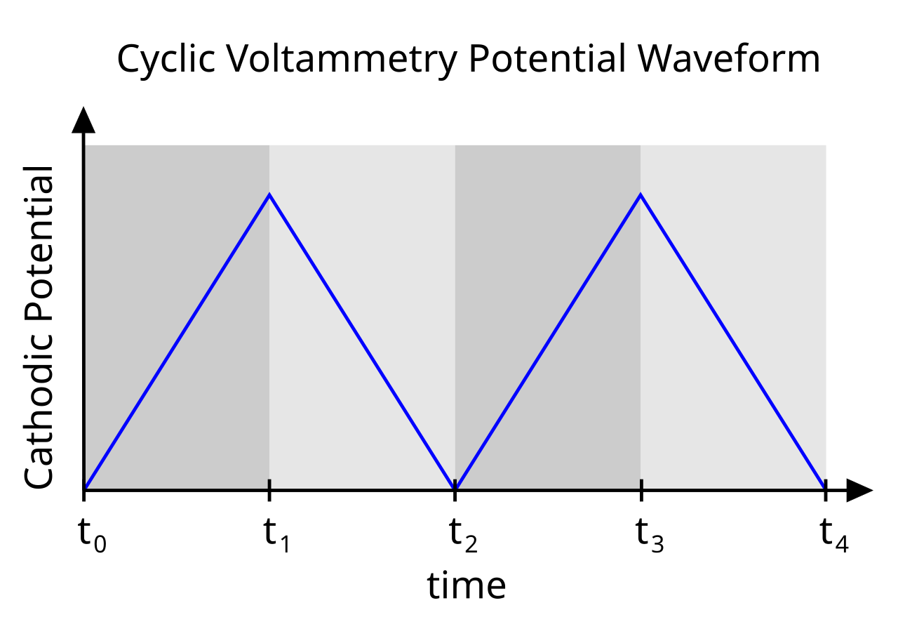
Cyclic voltammetry (CV) is a type of voltammetric measurement in electrochemistry where the potential of the working electrode is ramped linearly versus time in cyclical phases. Unlike linear sweep voltammetry, after the set potential is reached, the working electrode's potential is ramped in the opposite direction to return to the initial potential, and these cycles are repeated until a cyclic steady state is achieved. The current at the working electrode is plotted versus the voltage to yield the cyclic voltammogram, which is generally used to study the electrochemical properties of an analyte in solution or adsorbed onto the electrode, and to quantify the electrochemical surface area of catalysts.
- field
- Electrochemistry
- known_for
- Cyclic voltammetry (CV) as a technique for studying redox properties of analytes
- type
- Electrochemical measurement method
- key_equation
- Randles–Sevcik equation
- typical_setup
- Three-electrode cell (reference, working, counter electrode)
Lore & Background
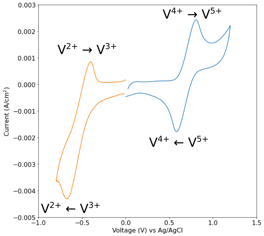
In cyclic voltammetry, the electrode potential is ramped linearly versus time in cyclical phases, with the rate of voltage change known as the scan rate (V/s). In a standard three-electrode cell, the potential is measured between the working electrode and the reference electrode, while the current is measured between the working electrode and the counter electrode. During the initial forward scan, an increasingly oxidative potential is applied, and the anodic current increases due to charging of the electric double layer, with a spike in current from oxidation of the analyte when the correct potential is reached. The current then decreases as the concentration of oxidable analyte is depleted near the electrode surface due to mass transport limitations.
Reader's Guide
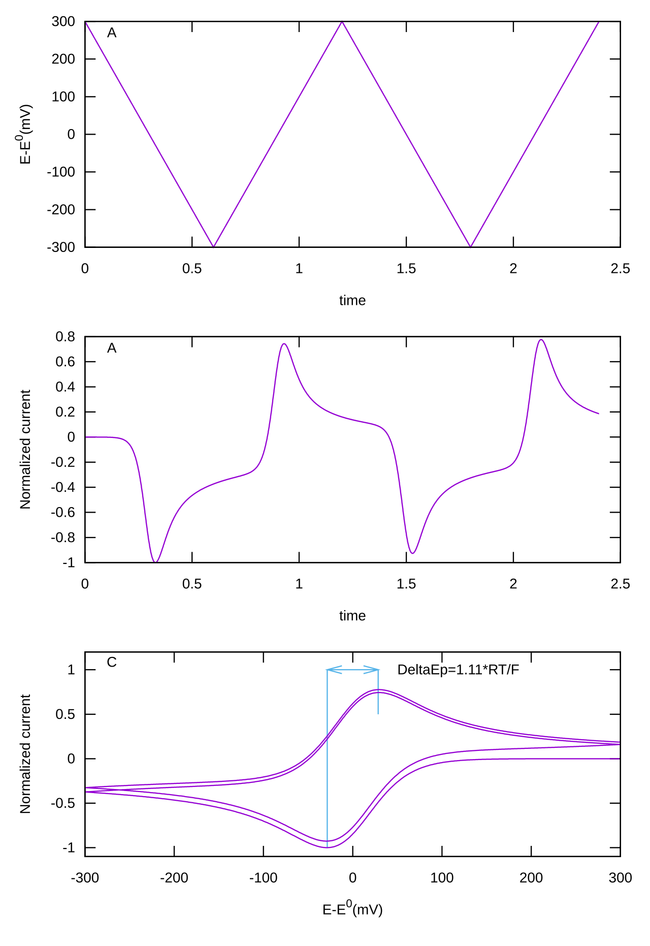
Cyclic voltammetry is a foundational technique in electrochemistry, used to characterize the redox properties of analytes in solution or adsorbed on electrodes. The resulting cyclic voltammogram often has a characteristic 'duck-like' shape, and comparing the oxidation and reduction portions allows determination of electrochemical parameters such as redox potential and reversibility. For reversible couples, the difference in peak potentials (ΔEp) is of particular interest, with an ideal 1e- couple giving ΔEp of 57 mV, though experimental values often approach 70 or 80 mV. The peak current is proportional to the square root of the scan rate when limited by diffusion, as described by the Randles–Sevcik equation. For nonreversible couples, thermodynamic potential is often deduced by simulation, and deviations from unity in peak current ratios indicate subsequent chemical reactions. The technique is also used to study adsorbed species, where at slow scan rates there is no peak separation and peak current is proportional to scan rate, useful for studying redox proteins. The utility of CV depends on the analyte being redox active within the potential window, and experiments are conducted in a cell with three electrodes in unstirred solutions.
Did You Know?
- In cyclic voltammetry, the potential is ramped linearly in both forward and reverse directions, unlike linear sweep voltammetry which only ramps in one direction.
- The cyclic voltammogram often has a characteristic 'duck-like' shape.
- For a reversible 1e- couple, the ideal difference between peak potentials (ΔEp) is 57 mV.
- The peak current in a diffusion-limited CV experiment is proportional to the square root of the scan rate, as described by the Randles–Sevcik equation.
The Cyclic Sweep and Three-Electrode Architecture
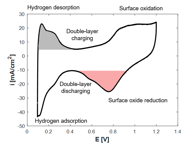
Cyclic voltammetry distinguishes itself from other voltammetric techniques through one defining feature: the potential of the working electrode is swept linearly with time in one direction, and then, upon reaching a preset limit, swept back in the opposite direction to the starting point. This back-and-forth cycling is repeated until the resulting current-versus-potential trace settles into what is called a cyclic steady state. The experiment is conducted inside a standard three-electrode cell, where the potential is read between the working electrode and a reference electrode, while the current is measured between the working electrode and a counter electrode. The rate at which voltage changes during each leg of the sweep is termed the scan rate, expressed in volts per second. During the forward, oxidative leg, the anodic current rises first because of double-layer charging, then spikes sharply once the potential is sufficient to oxidize the analyte in solution. After that peak, the current falls as the concentration of oxidizable species near the electrode surface is exhausted by mass-transport limitations. The raw data are typically plotted as current density in milliamperes per square centimetre against potential, corrected for Ohmic iR drop.
The Duck-Like Signature and Reading Reversibility
One of the most immediately recognizable features of a cyclic voltammogram is its so-called duck-like silhouette, formed by the paired oxidation and reduction peaks. On the reverse sweep, the analyte that was oxidized during the forward leg begins to be reduced again, producing a cathodic current of opposite polarity. The degree to which the two peaks mirror each other in shape is a direct indicator of how reversible the redox couple is: the more reversible the system, the more symmetric the two lobes appear. The potential gap between the anodic and cathodic peak maxima, denoted ΔEp, encodes important mechanistic information. For an ideal one-electron reversible couple, theory predicts ΔEp of roughly 57 mV and a full-width at half-maximum near 59 mV, yet real experiments commonly yield values closer to 70 or 80 mV because of finite electron-transfer kinetics and diffusion effects. In a perfectly reversible system the ratio of anodic to cathodic peak currents equals one, and the midpoint potential yields a thermodynamic half-cell value. Semi-reversible waves, where that ratio deviates slightly from unity, can still reveal richer mechanistic detail. The underlying polarization behaviour is described by the Butler–Volmer and Cottrell equations.
Diffusion-Limited Regimes and the Randles–Sevcik Window
When electron transfer at the electrode surface is fast enough that it does not bottleneck the reaction, the current becomes governed entirely by how quickly analyte molecules can diffuse through the solution to reach the surface. In that diffusion-controlled regime, the peak current scales with the square root of the scan rate, a relationship captured by the Randles–Sevcik equation. Practically, this means a cyclic voltammetry experiment probes only a thin diffusion layer hugging the electrode, sampling a very small volume of the bulk solution. If the current is instead limited by the kinetics of electron transfer rather than by mass transport, the peak current will show a different dependence on scan rate. To diagnose which regime is operative, practitioners perform a power-law fit of the maximum current against scan rate; an exponent of 0.5 confirms diffusion control, while a different exponent points toward kinetic limitations. The same mass-transport constraint is what causes the current to decay after the initial oxidation spike: once the oxidizable species immediately adjacent to the working electrode are consumed, replenishment depends on bulk diffusion, and the current falls accordingly.
Where CV Earns Its Keep: Applications and Analytical Reach
Cyclic voltammetry is not a single-purpose tool; its value spans several distinct electrochemical tasks. The most common application is probing the redox behaviour of a dissolved analyte or of a molecule that has adsorbed onto the electrode surface, revealing whether the electron-transfer process is reversible, quasi-reversible, or irreversible. Equally important is the use of CV to quantify the electrochemically active surface area of catalysts inside working electrochemical cells, a measurement critical for comparing catalytic materials. A fundamental prerequisite, however, is that the species under investigation must be redox-active within the potential window the experimenter chooses to scan; outside that window the technique simply cannot elicit a measurable faradaic response. Reversible couples, while straightforward to interpret, carry less mechanistic information than the more complex waveforms produced by quasi-reversible or irreversible systems. By comparing the shapes, peak separations, and current ratios of the oxidation and reduction portions of the trace, a wide array of electrochemical parameters can be extracted, making CV one of the most versatile workhorses in the electrochemist's laboratory.
Gallery
Frequently Asked Questions
Who is Cyclic voltammetry?
Cyclic voltammetry is a voltammetric technique in electrochemistry that drives the working electrode's potential linearly forward in time, then reverses the ramp to return to the starting potential, repeating this back-and-forth sweep. It is distinguished from a simple linear sweep by that deliberate reversal and repetition of the potential trajectory.
What are Cyclic voltammetry's powers/role?
Its core function is to probe the redox (electron-transfer) behavior of an analyte by recording the current that flows at the working electrode as the applied voltage changes. The resulting current-versus-voltage trace, the cyclic voltammogram, reveals oxidation and reduction potentials, reaction reversibility, and kinetic details of the electrochemical process.
How does Cyclic voltammetry's story end?
The measurement wraps up once the potential has been cycled forward and backward enough times to reach a cyclic steady state, at which point the current response stabilizes. The final deliverable is the cyclic voltammogram—a plot of working-electrode current against applied voltage that summarizes the entire experiment.
Why is Cyclic voltammetry important?
It is one of the most widely used tools in electrochemistry for determining whether a species undergoes reversible, quasi-reversible, or irreversible electron transfer. The Randles–Sevcik equation, which links peak current to scan rate, is a cornerstone relationship that emerged directly from this technique.
What is Cyclic voltammetry's typical setup?
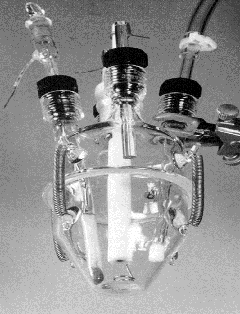
A standard CV experiment employs a three-electrode cell comprising a working electrode, a reference electrode, and a counter (auxiliary) electrode. A potentiostat holds the working electrode at a controlled potential relative to the reference while the counter electrode completes the current-carrying circuit.
More in Chemical Analysis And Spectroscopy 1-18
Spotted an error? Know more?
This is a living reference — every entry is fact-audited, and reader corrections feed straight into our audit queue. Suggest an edit · See this site's audit record